
 Industrial automation is a risky endeavor because it matches computers, which are very reliable and predictable, with plant equipment that can be less reliable and predictable. To further complicate matters, computers can only attempt to sense and control equipment through input and output devices that do not always work as expected and are sometimes the cause of process upsets.
Automation practitioners can also be hampered by resource-constrained legacy equipment, insecure communication protocols and antiquated Ladder Logic programming.
So what’s wrong with legacy equipment and applications?
It’s been working for many years, so why risk changing anything? Often the stimulus to replace existing automation is that the PLCs or hardware devices that have been in service for decades have finally been discontinued by manufacturers.
From a cost standpoint, the best approach might be to migrate the existing software onto a newer hardware platform and put it back into service. But is that always the right answer? At what point is the best decision to implement modern devices and development methodologies?
Some industrial automation seems quite simple; a pump or valve can be used to maintain the level in a tank. It becomes much more complicated when processes, consisting of many steps, are automated. An even more challenging project would be to automate a multi-step process on similar, yet non-identical process equipment.
A Unique Approach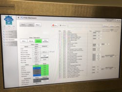
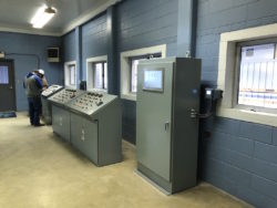
The Ouachita Water Treatment Plant Filter Improvement project in Hot Springs required implementation of an improved filter automation system including an automated backwash process.
There are a total of 9 filters: 6 of one style and 3 of a different style. Because of the differences in the construction of the filters and the plant hydraulics, each filter required similar but unique setpoints and configuration ranges for a multitude of parameters.
A fundamental aspect of the design philosophy was to model the various components of the system and then combine these components to provide a model of each filter. In addition, a simulation was built using the model components, so that the system could be tested and evaluated months before it was scheduled to be installed.
This was critical to the success of the project, because the various stakeholders were able to interact with the system and provide feedback significantly in advance of deployment. This modular approach also limited deployment risk, because any changes made to each “type” of equipment were automatically applied to all other instances of similar equipment.
The modular development philosophy is repeated throughout the system. Object-oriented programming techniques were utilized to develop components on the PLC. This approach virtually eliminated redundant code that would have resulted from a copy-paste-change style of implementation, which requires the developer to search and replace similar program elements manually. Data structures were created in the SCADA system that aligned with the objects created on the PLC.
To reinforce this link, the data structures in the SCADA system were given the same names as the PLC objects. Visual components were created in the SCADA system that provided a user interface for the various data structures. Finally, the data structures and visual components were combined to provide a visual representation of the model running on the PLC.
A consistent, modular approach simplifies change management, which increases system reliability and maintainability. Changes to the PLC model are generally applied to only the definition of each component, and these changes are automatically applied to all instances of that component throughout the system by the PLC development system.
If changes to the PLC model impact the SCADA data structures, only the definition of the data structure must be updated, and then changes are applied automatically by the SCADA system. If changes to the PLC model impact the SCADA visual components, these changes must only be made to the definition of these components and the changes are then applied automatically by the SCADA system.
For example, during deployment it was determined that one of the types of valves closed whenever the “open” signal was not present, instead of having separate “open” and “close” signals as expected. The PLC model for this valve type was changed and no other changes were required.
Another example is that a flow totalizer was requested after deployment. The PLC model was altered to include the flow calculation, the SCADA data structure was altered to add the new data element, and the SCADA visual component was altered to add the new data element. No other changes were required and the change was applied to system automatically by the PLC and SCADA development applications.
Increased Values of Reliability and Maintainability
For simple automation systems, a copy-paste-edit style of application development with legacy tools may provide the shortest initial development time in some instances, but a modular development approach adds significant value in the long term due to increased flexibility, reliability, reusability and maintainability; the added complexity of the model development simplifies the overall solution.
Sam Vandiver, PE is Vice President of Automation at Brown Engineers.
